1 SCOPE
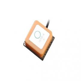
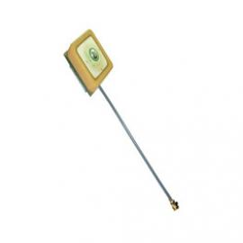
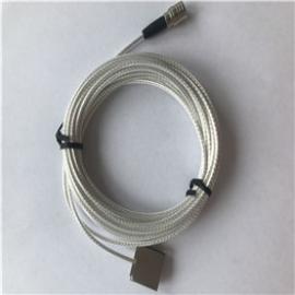
This specification shall cover the characteristics of the dielectric antenna element with the type GL1621R2540ABDB1-T.
2 PART NO.
|
PART NUMBER
|
CUSTOMER PART NO
|
SPECIFICATION NO
|
|
GL1621R2540ABDB1-T
|
|
|
3 OUTLINE DRAWING AND DIMENSIONS
3.1 Appearance: No visible damage and dirt.
3.2 The products conform to the ROHS directive and national environment protection law.
3.3 Dimensions
4 ELECTRICAL SPECIFICATIONS
4.1 Performance Characteristics
|
Items
|
Content
|
|
Nominal frequency MHz
|
1621.5±5.5
|
|
Center frequency MHz
(without tape on 70×70mm ground plane)
|
1623±3.0
|
|
-10dB Bandwidth MHz min
|
17
|
|
Return Loss at Center Frequency dB max
|
-15
|
|
Polarization Model
|
RHCP
|
|
Impedance Ω
|
50
|
|
Frequency Temperature Coefficient
|
20ppm/deg.℃ max
|
* Center frequency :-10dB bandwidth center frequency.
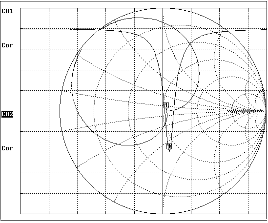
4.2 Impedance Characteristic

5 TEST
5.1 Test Conditions
Parts shall be measured under a condition (Temp.:20℃±15℃, Humidity : 65%±20% R.H.).
5.2 Test Jig

6 ENVIRONMENTAL TEST
|
No.
|
Item
|
Test Condition
|
Remark
|
|
6.1
|
Humidity Test
|
The device is subjected to 90%~95% relative humidity 60℃±3℃ for 96h~98h,then dry out at 25℃±5℃ and less than 65% relative humidity for 2h~4h. After dry out the device shall satisfy the specification in table 1.
|
It shall fulfill the specifications
in Table 1.
|
|
6.2
|
High
Temperature
Exposure
|
The device shall satisfy the specification in table 1 after leaving at 105℃ for 96h~98h,provided it would be measured after 2h~4h leaving in 25℃±5 ℃ and less than 65% relative humidity.
|
It shall fulfill the specifications
in Table 1.
|
|
6.3
|
Low
Temperature
|
The device shall satisfy the specification in table 1 after leaving at -40℃ for 96h~98h,provided it would be measured after 2h~4h leaving in 25℃±5 ℃ and less than 65% relative humidity.
|
It shall fulfill the specifications
in Table 1.
|
|
6.4
|
Temperature
Cycle
|
Subject the device to -40℃ for 30 min. followed by a high temperature of 105℃ for 30 min cycling shall be repeated 5 times. At the room temperature for 1h prior to the measurement.
|
It shall fulfill the specifications
in Table 1.
|
|
6.5
|
Vibration
|
Subject the device to vibration for 2h each in x、y and z axis with the amplitude of 1.5mm, the frequency shall be varied uniformly between the limits of 10Hz~55Hz.
|
It shall fulfill the specifications
in Table 1.
|
|
6.6
|
Soldering Test
|
Lead terminals are heated up to 350℃±10℃ for 5s±0.5 s with brand iron and then element shall be measured after being placed in natural conditions for 1 h. No visible damage and it shall fulfill the specifications in Table 1
|
It shall fulfill the specifications
in Table 1.
|
|
6.7
|
Solder ability
|
Lead terminals are immersed in soldering bath of 260℃~290℃ for 3s±0.5s . More than 95% of the terminal surface of the device shall be covered with fresh solder.
|
The terminals shall be at least 95% covered by solder.
|
|
6.8
|
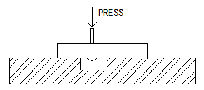
Terminal Pressure Strength
|
Force of 2kg is applied to each lead in axial direction for 10s±1 s (see drawing). No visible damage and it shall fulfill the specifications in Fig 1
|
Mechanical damage such as breaks shall not occur.
|
|
Item
|
Specification After Test (MHz)
|
|
Center Frequency change
|
±2.0
|
|
-10dB Bandwidth Change
|
±2.0
|
7. PACKAGE
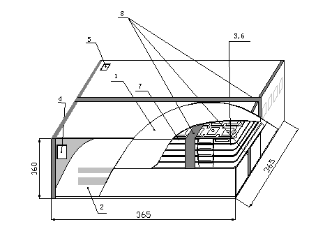
To protect the products in storage and transportation,it is necessary to pack them(outer and inner package).On paper pack, the following requirements are requested.
7.1 Dimensions and Mark
At the end of package, the warning (moisture proof, upward put) should be stick to it.Dimensions and Mark (see below)
A GPS ceramic antenna is a crucial component in navigation systems. It plays a vital role in receiving and transmitting signals between the GPS device and satellites. The ceramic material used in these antennas offers several advantages, such as high durability, temperature resistance, and excellent signal reception. With its compact size and lightweight design, the GPS ceramic antenna is ideal for various applications, including automotive, aviation, and marine industries. Its reliable performance ensures accurate positioning and navigation, even in challenging environments. Whether you are exploring new territories or simply finding your way around the city, a GPS ceramic antenna is a reliable companion that enhances your navigation experience.